There are many people with 400 amp service that either have a single monitor on only one 200 amp panel or use dual monitors with 2 accounts.
My feeling is a lot of people are missing out and could be using a single monitor for their entire 400 amp service.
From what I’ve seen and read, most are looking at the panels where the breakers are for the only place to install Sense. By taking their monitor and installing it or the clamps at the meter socket or even right before their meter, they could use just one account and monitor.
There are also others ways to accomplish a single setup.
I hope those that have theirs installed with just one Sense will share their stories and picture to help others.
3 Likes
Hi there,
Just re-installed mine last weekend. I originally had planned to do the two sense setup as I have a parallel feed, but after reading the success of people going pre-meter I went back and took a second look.
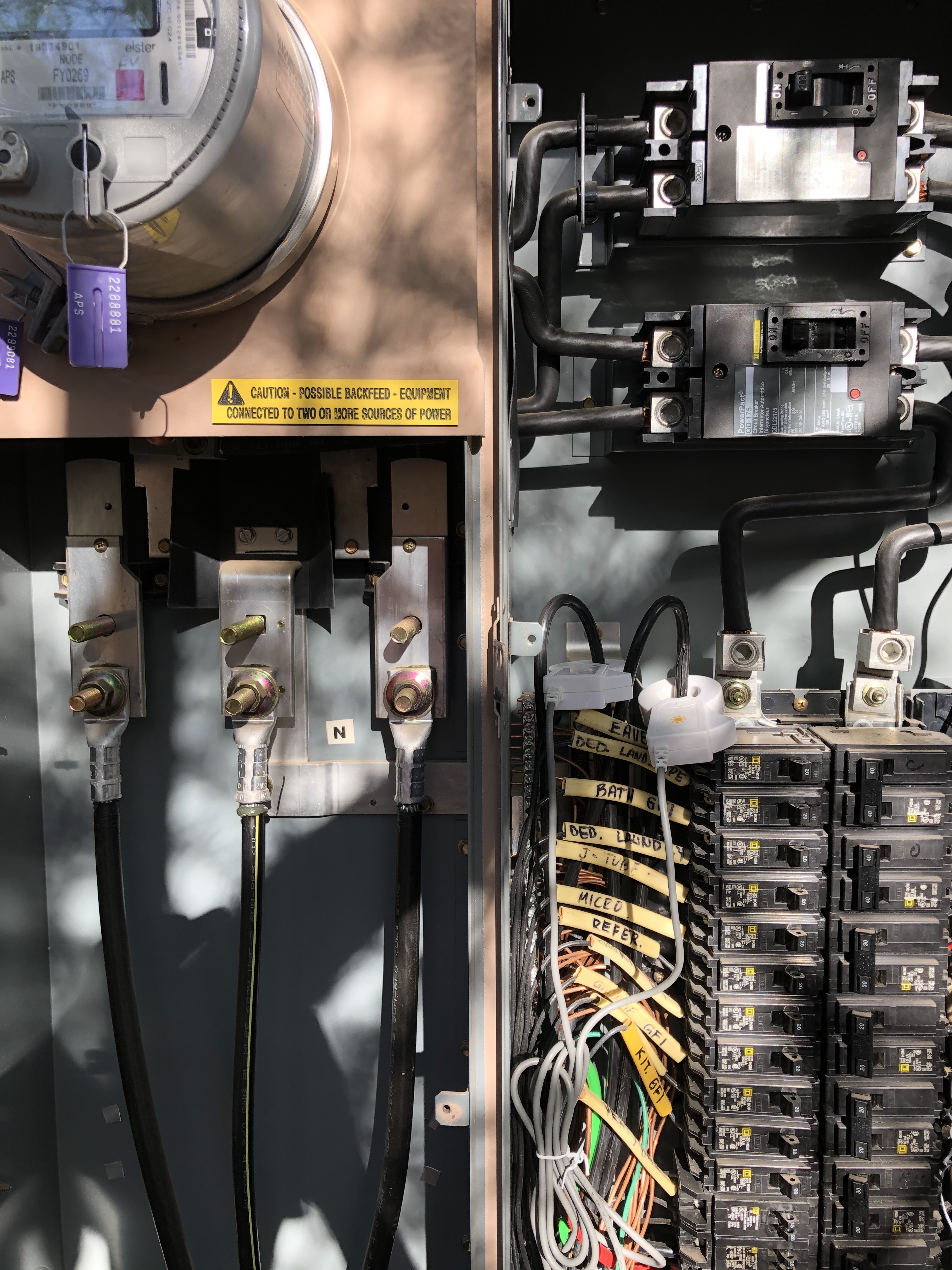
I have a setup where a single feed gets split after the meter, both runs go to the main panel where both 200 amp breakers live (the second panel is then fed back from that breaker.) Initially I tried to put the clamps in the breaker panel, in the image you can see the feeds from the meter are pretty close together when they come out of the meter, but unfortunately not close enough to get the clamps around them.
Then I looked at the service panel below the meter. It looks like the clip they “lock” the panel with was the same clip they used when the house was built and after years in the sun it basically turned to dust when I touched it. So, I opened up that panel and the clamps fit easily around the feed. I was able to thread the connector through the grommets that the feed lines from the meter use, so I didn’t have to drill or anything.
I took the photo before I attached the clamps to the feed lines, but you can see the solar clamps on the upper left side of the breaker panel. There is another breaker panel to the left of the meter that is out of sight of the photo.
So far it seems to work pretty well. Still new setup, so nothing but 3 fridges and 3 AC units. I don’t think I have any clipping issues yet, peak usage so far is 39,815 w.
I don’t know much, but I am happy to answer any questions. (and if I did something wrong, happy to be taught.)
2 Likes
That’s great!
Glad your situation allowed for the conversion to a single monitor. I don’t think you’ll have any problems or “clipping” either.
The pics don’t really show where you put the clamps but I assume they are right under the meter in that panel?
Having six detections since last weekend is terrific.
Just so others will know, which reset did you use?
Was it the data reset or factory?
Correct, the clamps are under the meter, attached to the the two outside feeds. (the one with the yellow stripe doesn’t get a clamp, the other two do.
I will try and remember to get a photo with the clamps wires in over over the weekend to update.
I used the data reset.
Another trouble I overcame, I have a number of access points around the house, and although the Sense guidance that it has to be locked to one AP is well communicated and certainly no secret, I admit I banged my head against the wall too many times trying to figure out why my sense kept going offline. I isolated an AP that had a 2.4ghz channel for the sense and everything is happy so far.
I run dual 200 amp circuits into my house. The problem is that the transformer is in the Far side of the yard and from there to my house there are two 200 amp distinct circuits. So… no single point where I can install the Sense CTs.
What I did was splice two sets of CTs in series (not in parallel- tried in parallel, but Sense did not recognise the CTs at all) and let it loose. I know this is an unsupported config, but Surpassingly it all works well, discovers new devices as expected, measures total consumption correctly, etc. In a word- success. It may clip over 200 amps, but it is for a very short period of time and does not change my measurements and stats enough for me to care.
2 Likes
Thanks for your story here. I’ve wondered about using clamps in series but have only one monitor.
Maybe @RyanAtSense can forward this to their team. Maybe your perseverance has found something that are unaware will work.
Any chance you have a photo of how you did this? Did you just buy the solar sensors to splice?
I bought the solar clamps and spliced them in series. Seems to be working like a charm.
I have the same issue. Want to try the same approach. Can you post a photo? Want to see what you mean by “spliced them in series”
thanks in advance
@jenkins.robert - would you be willing to share a picture of how you spliced your clamps with me? Thanks!
N
Can someone who has done the splice show a picture of how they spliced the clamps? This would help a lot of us who are trying to make this configuration. Thanks!
If you don’t have solar, you can now buy the Flex add-on sensors and use the solar port. Installing Sense with 2x200A service
I have solar
Any way you can hook the Sense CTs to your 400A service mains ? I couldn’t do that after my PG&E meter because the bus bar is too large, but I could do it inside the meter box. That works just fine for me with solar.

1 Like
Here’s the information I learned while doing this with other current sensing devices. You could potentially damage your sense monitor so do this at your own risk.
There’s a lot to think about while attempting this. The direction the spliced sensors are facing and the leg you place them on determines if current shows as positive or negative or lower than it should be because one is positive and one is negative. If you splice two current sensors and place them facing the same direction on leg 1 in one panel and leg 1 in the other panel, current is added (i.e. 71 amps + 42 amps = 113 amps). If one is facing the opposite direction on the same leg in different panels current is going to be negative on one and positive on the other and could result in a negavive value (i.e. -71 amps + 42 amps = -29 amps). If I were doing this, I’d splice two of them, place them facing the same direction on the same legs in different panels. Do the same for the other two but place them on the second leg of each panel facing the same direction. This will give you positive current numbers for both legs. If you are getting a negative or your total current is lower than expected, you probably have a sensor or both sensors reversed.
I did this when I created my own energy monitoring device using open energy monitor and my custom made emontx. Worked perfectly. I installed both sense and smappee around the same time. Smappee sold a y-cable specifically for this configuration and they had instructions with images of how to do it. Of course, I cannot find them anywhere on the internet now. There are different ways you can position the sensors to get the same end results such as the spliced sensors in the same panel but with one reversed. However, since sense also monitors voltage on each leg, it makes more sense to keeps the spliced CT sensors on the same leg, same direction in different panels.
I don’t know how much current the sense monitor can handle on each input but if they can only handle 200 amps each and you are pushing over 200 amps, you could potentially fry your sense monitor. However, since many people install them at the meter to handle two panels, that’s probably not going to happen.
No, the meter is tiny compared to what you are showing in your picture and I cannot see any place to connect the clamps after the meter as the line splits somewhere below ground level and reemerges split to the 2 breaker boxes
The connection in series is not too bad … each clamp has two wires - a red wire and a black wire. So let’s label 2 sets of clamps - 1A and 1B for the first box left and right side and 2A and 2B for the second box left and right side … assume all clamps are on in the same direction and manner.
Now to make the serial connection what I did was:
- Cut the connection adapter on clamp 2A exposing the black and red wires. Strip these wires to expose the aluminum wiring underneath.
- On clamp 1A cut the red wire between the adapter and the clamp and connect the clamp side of the red wire to the black wire of clamp 2A.
- Take the red wire of clamp 2A and connect it back to the red wire of clamp 1A on the adapter connection side.
- Repeat with clamp 2A and 2B.
You will now have two clamps connected in series. Everything seems to work fine with one issue … in testing sometimes when I turn on some switches the power seems to be flipped i.e. the power declines when the switch is turned on and increases when the switch is turned off. I do not understand this behavior and I have verified the clamp orientation and the wiring of the in series clamps. Any idea what is wrong?
** UPDATE
I figured out what is going on. I assumed that the two meters would be identical in all respects but they are not. The two input wires in the first meter are black and then black with a red stripe. On meter two the first input wire is black with a red stripe and then black (i.e. reversed to the first meter). Once I fixed the clamps so that both pairs were on the identical input wire everything started to work fine …
I have had two Sense’s on two 200 amp panels for a single house for several years and had discovered many devices. I recently got the extender cables to be able to use one sense monitor for the 400 amp service. I was thinking it would be as easy as to plug the new cables in and it would start reading them. This was not the case. It seems that I had to reset the Sense monitor and reconfigure it, so essentially starting from scratch on recognizing device. Has anyone else had this experience? Is there a way to retain the devices discovered when converting from two Sense’s to one Sense on a 400 amp service.
@mr396, I had a different experience. I have a 400A household with two 200A subs and with solar. I put my original Sense on the 400A feed to my meter and the second set of CTs on my solar backfeed (a typical Sense Solar install). I later bought a second Sense to try out the the split 200A capability. Because both ports were used for mains, there is no solar input, so all that system sees is net power usage, plus it had to be installed on a new account.
My take is that it is very difficult to keep device models around from an earlier install configuration because phases/legs and potentially polarities can change for each detected device after a new configuration. The phase/leg info is baked into the on and off signatures…