Thanks for the details to assist with the installer!
My systems has been installed since December 2019 and i only consume about 26kWh from the grid on the last bill
Thanks for the details to assist with the installer!
My systems has been installed since December 2019 and i only consume about 26kWh from the grid on the last bill
Your usage could be because you used more than the 8000 watt the inverter could generate.
Is that amount constant over your last year ?
26000Wh /31 day = 838Wh/day /24 hr = 35 watt average
The screenshot you showed was 300 watt so almost 9 times as much.
I don’t have the experience yet with my inverter so can’t give you comparison.
Keep us (me) posted about any progress (or not)
The only two circuits on the grid panel are the inverter and the sense monitor.
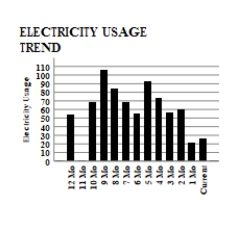
I have be moving circuits around now that im understanding the system and my usage. This is the second month of 20+ kWh since i made the last set of changes and removed the dryer circuit.
The is what my usage looked like before and i was off grid for one when i was testing out the system capabilities.
I will keep the group posted once the installer checks out the installation.
Thanks again!
Do you have a drawing how things are hooked up?
Did sense provide you with some kind of drawing how to hook it up ?
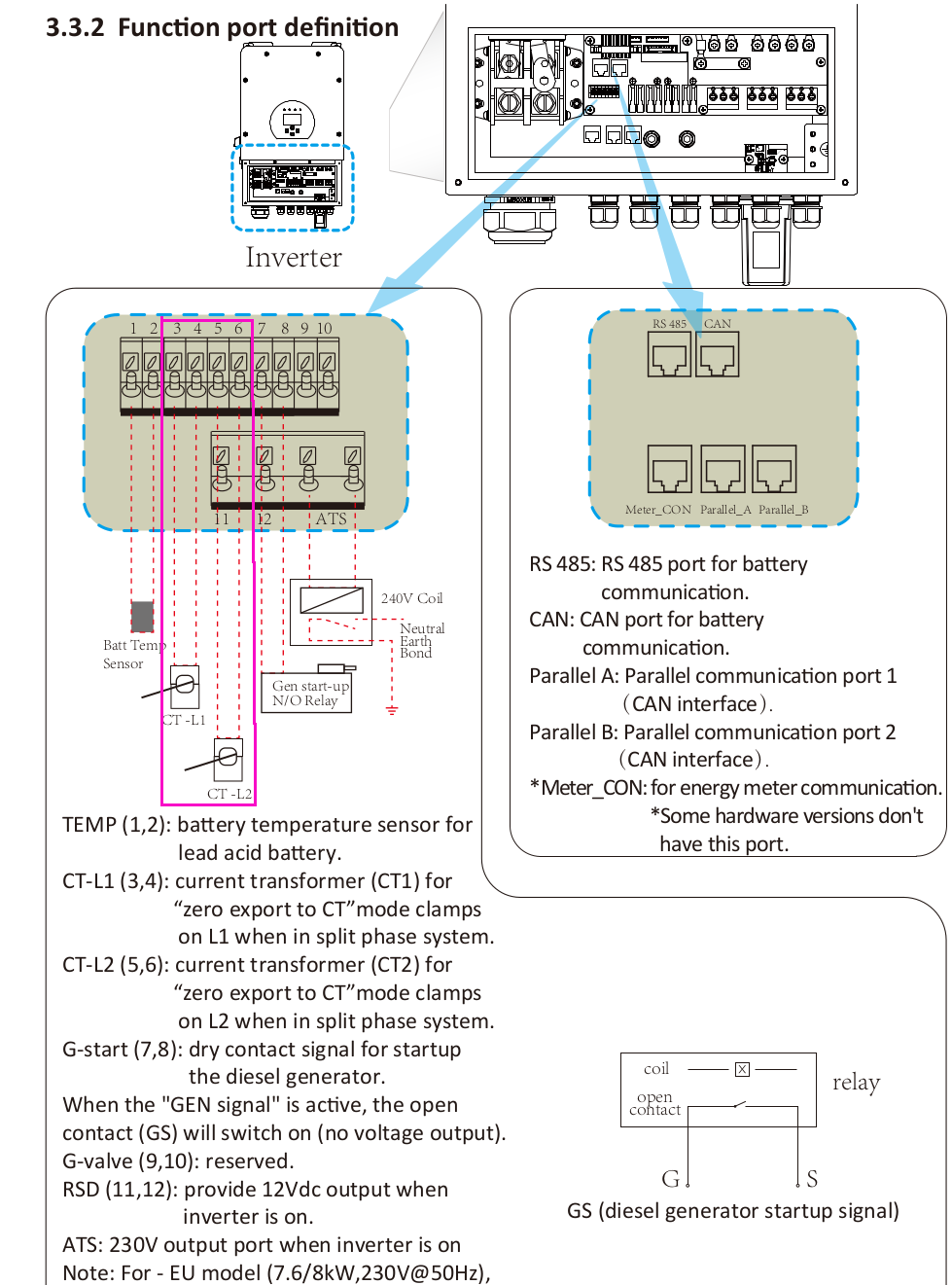
In the hookup diagram I got the model number of your inverter and downloaded all the info.
Your inverter is a little bit different from mine.
Yours has 2 mppt’s with 10kW PV, mine has 4 mppt’s with up to 12kW.
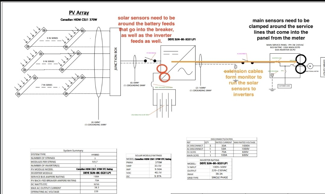
Here is an updated version of the location of CT1 & CT2 hookup on your inverter that the installer could check, highlighted by me in purple
Oh wow.
This is going to be a long thread.
The more info emerges, the more complicated it gets.
Your schematic is not how it is IRL.
Let me start by saying I don’t understand one thing from the feedback of the sense people.
“solar sensors need to be around the battery feeds that go into the break as well as the inverter feeds as well”
This might be the case with tesla powerwalls because everything is AC coupled, but your inverter CLEARLY show a DC & AC sign and the place of the orange circles for the SOLAR CT’s looks like they indicate you should put them around the DC cables and I guarantee you, that won’t work.
You also told us :
“I have two panels, main panel with a few 220v circuits that are off and not used at the moment. And the distribution panel that is powered solely from solar and battery backup for the house.”
In the schematic you posted there is only one panel and it is the main panel and all the house loads are connected to it.
Sorry for my messy drawing, i am clearly not good at this. I even tried to draw the 2 circles where I think the CT’s are located.
But I think this is a better representation of how your system is wired:
Can you verify that ?
Yes, i have a sub panel with loads for the house
there are 2 wires (yellow & red) going through the sense solar pv’s .
Can you tell me what those 2 wires are connected to?
The yellow go up the most right conduit to your inverter it seems
like I wrote before: The feedback from Sense support was from someone who didn’t understand your setup. They thought your battery setup was AC coupled (eg tesla powerwall)
I hope sense support reads this as well.
red from the battery == DC
Sense can only detect AC
So only the yellow wires should be going through those sense solar CT’s
If this fixed some of your readings, you should follow up to sense support and show them this thread.
Thanks and will i follow-up with Sense Support
btw: those red wires can not be your battery wires.
For 8000 watt / 48 volt = 166 amp.
According to https://www.cerrowire.com/products/resources/tables-calculators/ampacity-charts/
what would be 00 or 2/0 awg cable that is needed.
Those are the cables on the left below the inverter.
My guess is those red wires are going to the switch on the right side of the inverter below your sub panel.
Without an accurate schematic of your setup (where is the transfer switch in your diagram ?) i am afraid nobody can give you any solid advice
Yes, you’re correct. The installer just told me that they are the grid connection to the inverter.
He will make the change and remove them from the Sense CT.
Will your installer update the schematic to include the transfer switch?
Yes, he make all the necessary changes
Now I’m regretting asking questions based on the subject matter.
@sensesupport made some changes today at 11:30AM to my setup and screwed up everything.
They have mixed up my home with grid energy and is refusing to fix it because my monitor is in Jamaica and their service is optimised for USA and Canada.
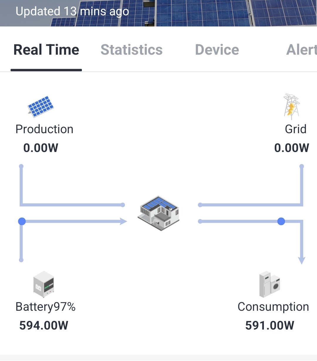
Today after they made changes:
Tonight showing energy from battery to grid instead of house:
From my inverter app:
Ehh… wait what ?
They change something, it is over obvious it is now incorrect and they refuse to reset to the old state?
That is weird and very customer unfriendly.
If you are in a country where they officially don’t deliver the equipment and don’t want to do support, the least would be to restore it to the old situation and then tell you “sorry, no support”
But this is very unprofessional imo.